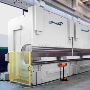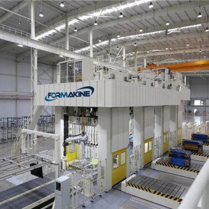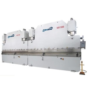
H Frame Link Drive Servo Stamping Press
Standard Configuration
1. Wet clutch device
2. Oil pressure overload protection
3. The slide adjusts the locking device
4. Automatic lubricator
5. Balance cylinder feeding device(manual)
6. Air injector3/8b 1
7. Air Outlet 3/8b 1
8. Touch panel
9. Electronic crankshaft angle display
10. Emergency stop button
11. One two-handed buttom table(move, fix or rotate)
12. Error detection interface (I/O standby interface)
13. Power socket (220V three holes, two holes)
14. Production counter(6 digits)
15. Production preset counter(6 digits)
16. Database(Available for 100 molds)
17. Electronic press speed indicator(SPM)
18. Out of range function detection circuit (TDC detection)
19. Front light curtain(Made in China)
20. Anti-Vibration Pad(Made in China)
21. Mechanical Pointer
22. Disc motor slide adjustment
23. The main loop free interference
Optional Accessory Devices
1. Tonnage meter(Electronic display)
2. Air cushion device
3. Hydraulic die locking device
4. Die moving support
5. Die changing trolley
6. Peripheral automation
7. IPC(Remote diagnosis function/program version upgrade)
8. Mold area light
9. Special power supply
10. Front and rear safety doors/fences/ladders
11. Slide knocking device
12. The quantity of two hands press button stations adding
13. Mold safety plug
14. Rear light curtain (Made in China)
Product Specifications
|
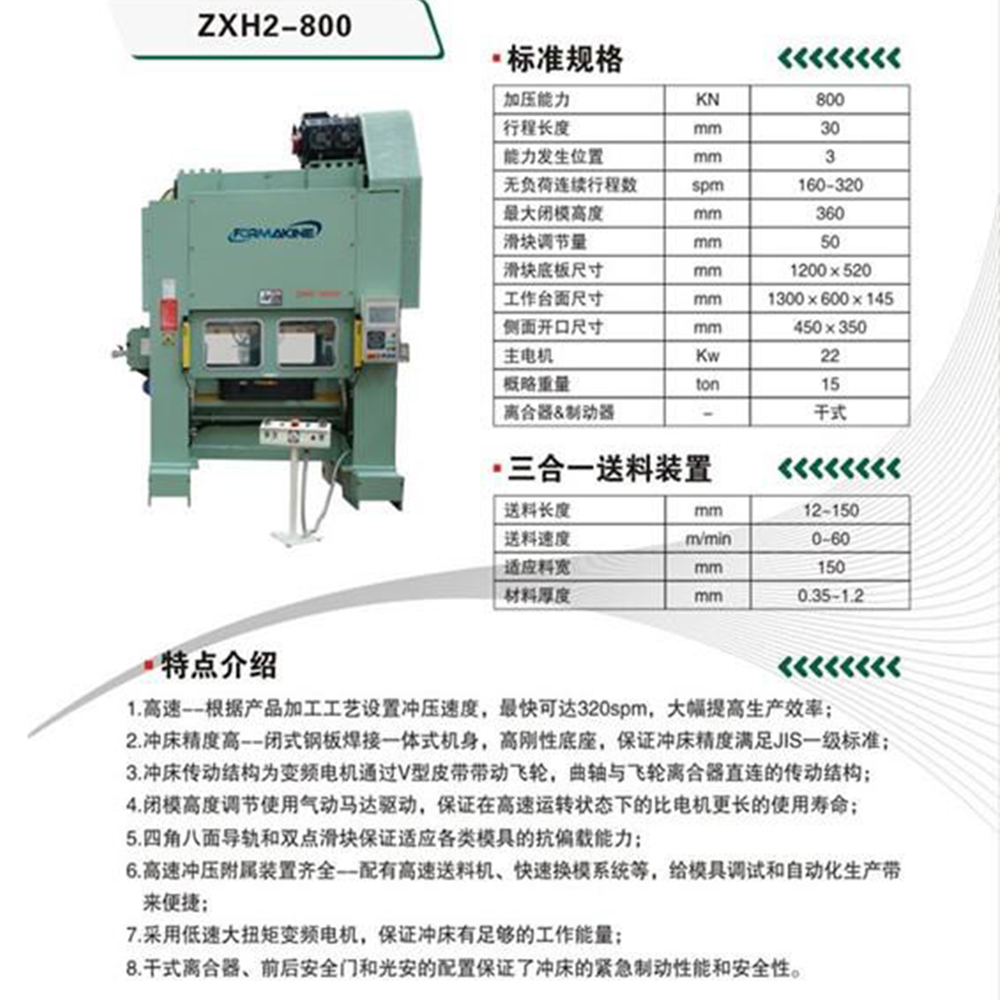
Straight Side High Speed Press |
|||||||
| ModelParameter |
Point & 3-Point |
||||||
| ZXH2-800 | ZXH2-1250 | ZXH2-2200 | ZXH3-3000 | ZXH3-2200 | ZXH3-3000 | ||
| Nominal Force | KN | 800 | 1250 | 2200 | 3000 | 2200 | 3000 |
| Nominal Force Distance | MM | 3.2 | 3.2 | 3.2 | 3.2 | 3.2 | 3.2 |
| Continuous Energy | J | 800 | 1200 | 2200 | 3000 | 2200 | 3000 |
| Stroke Length | MM | 30 | 30 | 30 | 30 | 30 | 30 |
| Unloaded Continuous Stroke Number | SPM | 200-600 | 160-500 | 160-450 | 120-400 | 160-450 | 120-400 |
| Die Height | MM | 400 | 420 | 470 | 520 | 470 | 520 |
| Slide Adjustment | MM | 50 | 50 | 50 | 50 | 50 | 50 |
| Slide Area (LR*FB) | MM | 1200*550 | 1400*600 | 2000*700 | 2300*800 | 2000*700 | 2300*800 |
| Bolster Area (LR*FB) | MM | 1200*750 | 1400*850 | 2000*950 | 2300*1000 | 2000*950 | 2300*1000 |
| Bolster Area Thickness | MM | 150 | 160 | 200 | 220 | 200 | 220 |
| Max. Upper Die Weight | KG | 500 | 500 | 1200 | 1500 | 1200 | 1500 |
| Side Opening(FB*H) | MM | 1000*250 | 1100*280 | 1600*350 | 1900*400 | 1600*350 | 1900*400 |