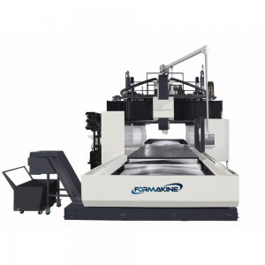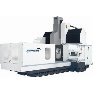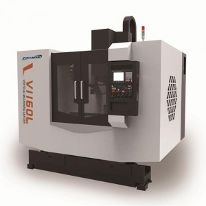
Portal CNC Milling Machining Center
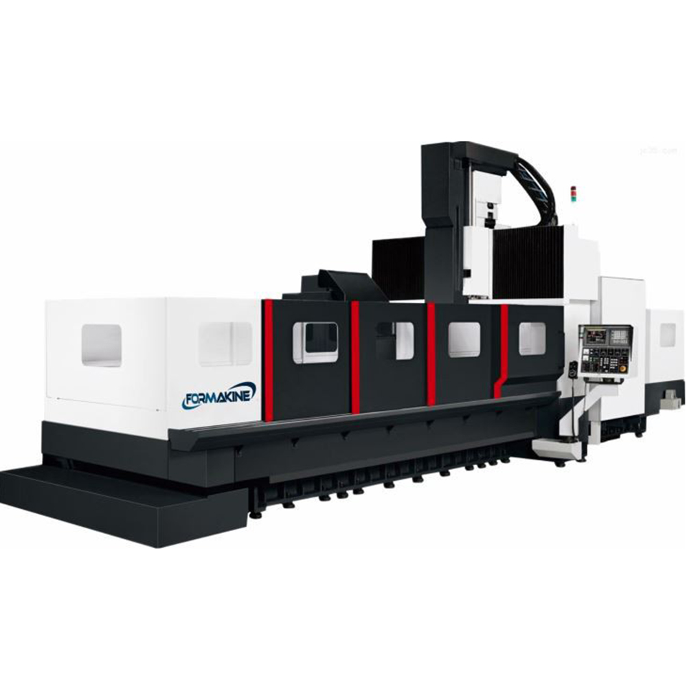
Product Description
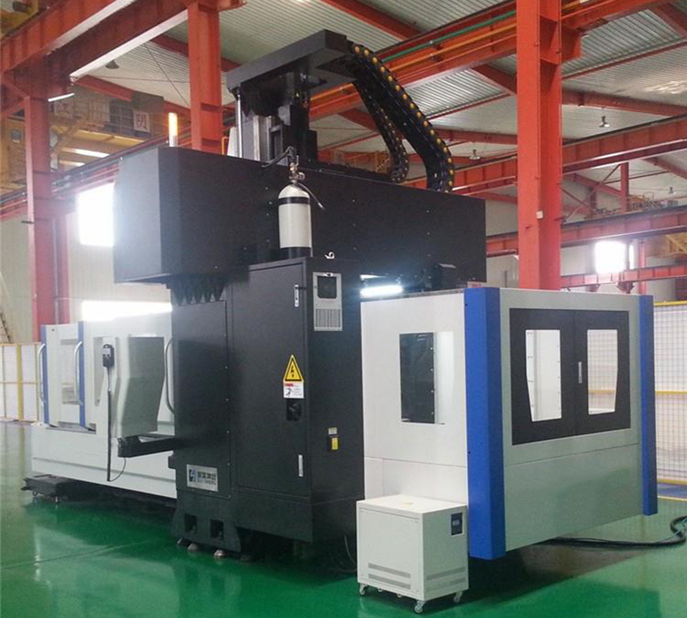
Portal CNC Milling Machine Center
Widely used in the aviation, auto, precision molding industries. It can provide a high-performance mechanical system and a software interface which can be operated easily. This provides multiple choices that will allow you to fully realize the high precision dream.
Technical Parameters
|
Specifications |
|
|||
|
Machine Type |
Unit |
YFM2018 |
YFM2518 |
YFM3018 |
|
Worktable |
||||
|
Worktable (Length×Width) |
Mm |
2000×1500 |
2500×1500 |
3000×1500 |
|
Maximun Load Of Table |
Kg |
8000 |
10000 |
12000 |
|
T-Slot |
Mm |
7-22×200 |
||
|
Triaxial Itinerary |
||||
|
Gantry Width |
Mm |
1800 |
||
|
Travel For X/Y/Z Axis |
Mm |
2000/1800/900 |
2500/1800/900 |
3000/1800/900 |
|
Distance From Spindle Nose To Table Surface |
Mm |
150-1050 |
||
|
Feed System |
||||
|
CNC System |
|
FANUC Oi MD |
||
|
Rapid Shift Of Axis Of X/Y/Z |
M/Min |
12/12/10 |
||
|
Maximun Cutting Feed Speed |
M/Min |
7 |
||
|
Automatic Tool Transform System (CNC Milling Without) |
||||
|
Standard Tool Quantity |
Piece |
BT50/24 |
||
|
The Larges Diameter Cutter Knife/Length |
Mm |
Φ110/300 |
||
|
Tool Exchanging Manner |
|
Pneumatic |
||
|
Maximum Tool Weight |
Kg |
18 |
||
|
Precision |
||||
|
Positioning Accuracy |
Mm |
0.021 |
||
|
Accuracy Of Repeated Positioning |
Mm |
0.02 |
||
|
Guide Form And Specifications |
||||
|
X/Y/Z-Axis Guide Specifications |
|
2-55(X)/2-55(Y)/Z Axis Hard Rail |
||
|
Spindle System |
||||
|
Spindle Specifications |
|
BT50/Φ190 |
||
|
Speed With Belt Drive Milling Head |
R.P.M |
6000 |
||
|
Motor Power Of Spindle |
Kw |
15/18.5 |
||
|
Air Pressure |
||||
|
Requirements For Air Compressing |
Kg/Cm² |
≥6 |
||
|
Air Pressure Flux |
M³/Min |
≥0.5 |
||
|
Machine Specifications |
||||
|
Integrated Weight |
Kg |
19000 |
21000 |
23000 |
|
Overall Dimension (Length×Width×Height) |
Mm |
6195×4200×4580 (Travel Peak) |
71400×4200×4580 (Travel Peak) |
8150×4200×4580 (Travel Peak) |
|
Standard Fittings |
|||
|
FANUC Control System |
Water Tank Cooling Device |
Working Lamp |
Outer Protective Cover |
|
Three-Color Warm Lamp |
LCD |
Tool Box |
Operating Manual |
|
Spindle Blowing Device |
Handheld Air Gun |
Electric Control Cabinet |
Transformer |
|
Pneumatic Part |
Sprial+Chain Chip Cleaner |
Spindle |
Screw |
|
Heat Exchanger For Electrical Cabinet |
RS-232 Standard Output Interface |
Automatic Lubricating Device |
Manual Pulse Generator |
|
Optional Fittings |
|||
|
CNC System Siemens/ Mitsubishi |
Automatic Tool Changer Disc Type / Chain Type |
Water Outlet From Spindle Center |
Disc Type Oil-Water Separator |
|
Air Conditioner For Electrical Cabinet |
Full-Enclosed Optical Scale Detecting System |
Automatic Tool Length Measuring System |
Manual/Semi-Automatic Right-Angle Head |
|
X/Y/Z Axis Optical Scale |
Toolholder In Oilway |
Oil Mist |
ZF Gearbox |
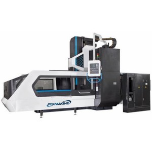
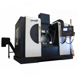
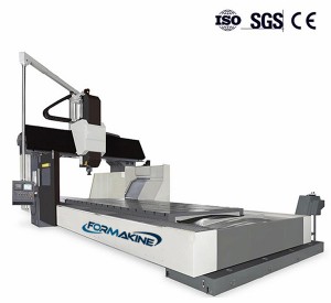
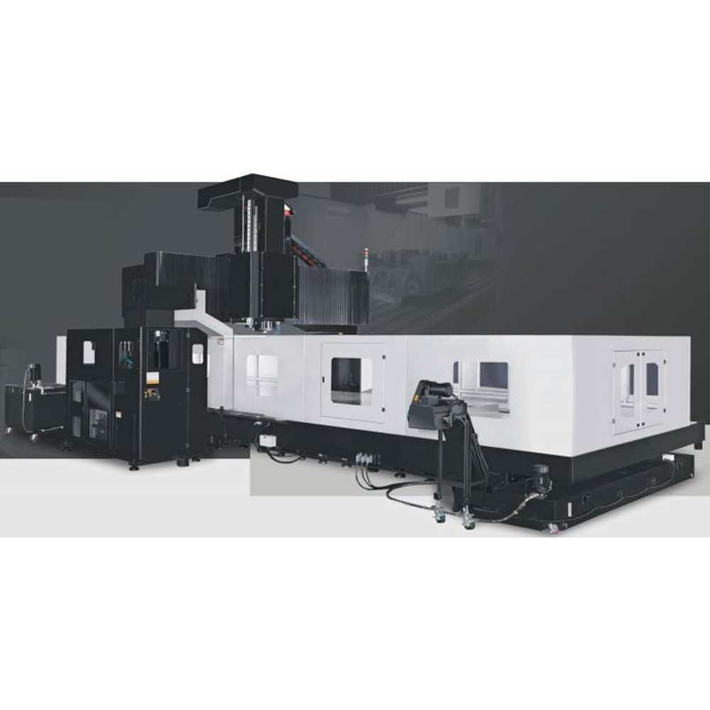
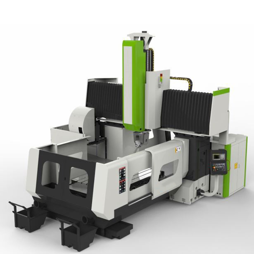
Picture Display
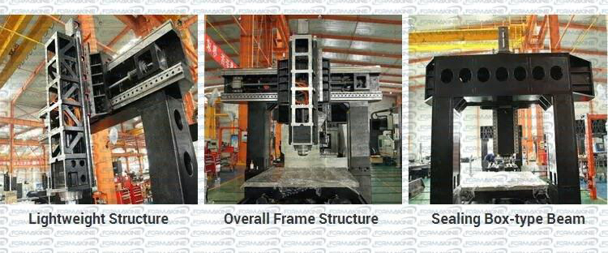
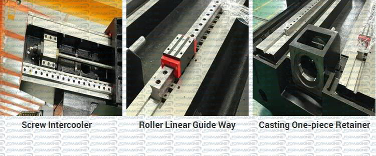
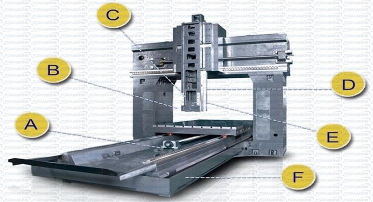
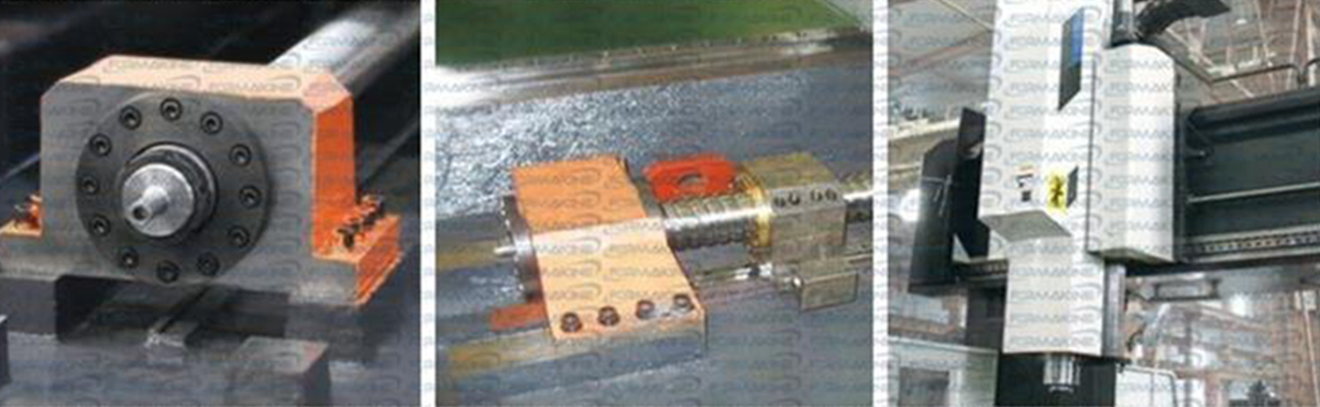
Structure
The structure of machine tool is analyzed with ANSYS at all stages from foundation design to guarantee of high-speed and high-precision continuous machining. A simulation test for deformation produced when the center of machine tool bears load is conducted to guarantee excellent bending rigidity of machine tool.
|
Optional external encoder realizes closed loop control |
Screw supporting structure is designed for above more than 5 meters (including 5 meters) gantries. |
All gear form main transmission is optional. The optional Z axis rails rail pretensioning structure the patent technology |
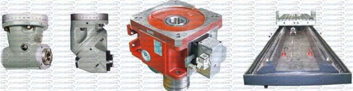
|
Optional 90° milling head realizes five-face machining. Optional universal milling head realizes multi-angle machining |
Optional German ZF gearbox widens machining range. |
As standard each Formakine gantry machining center is equipped with two spiral chip cleaners and one chain chip cleaner. |
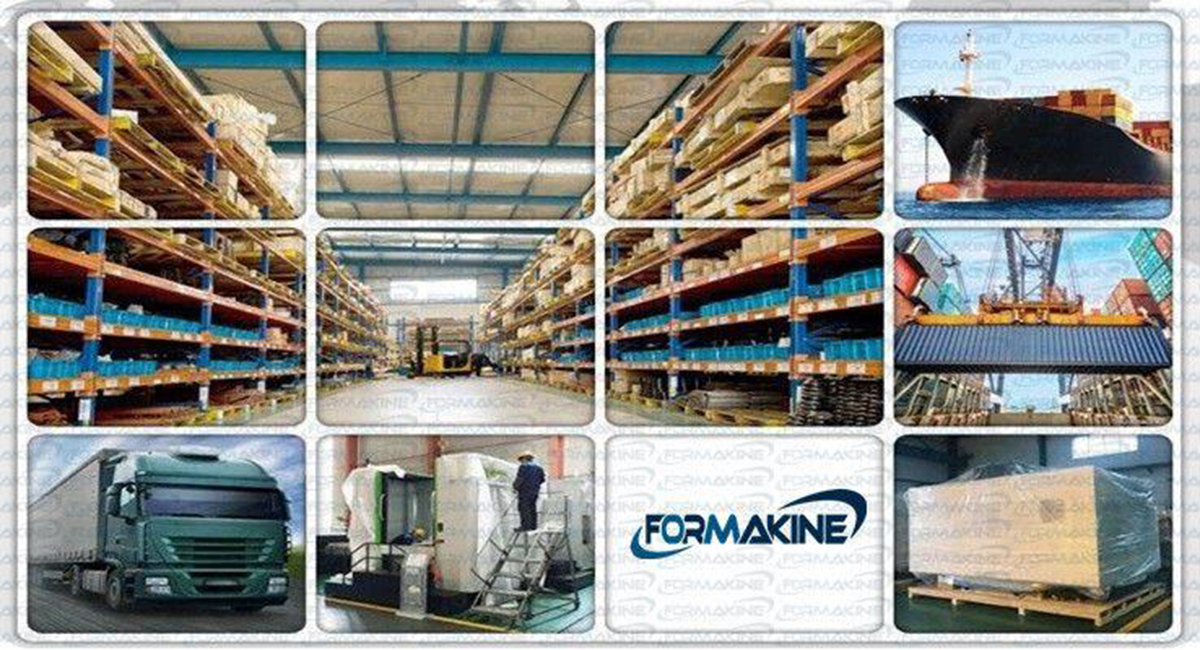
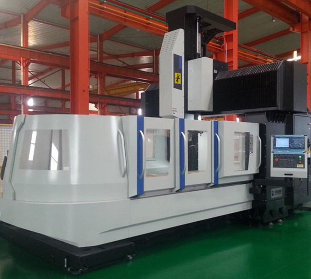
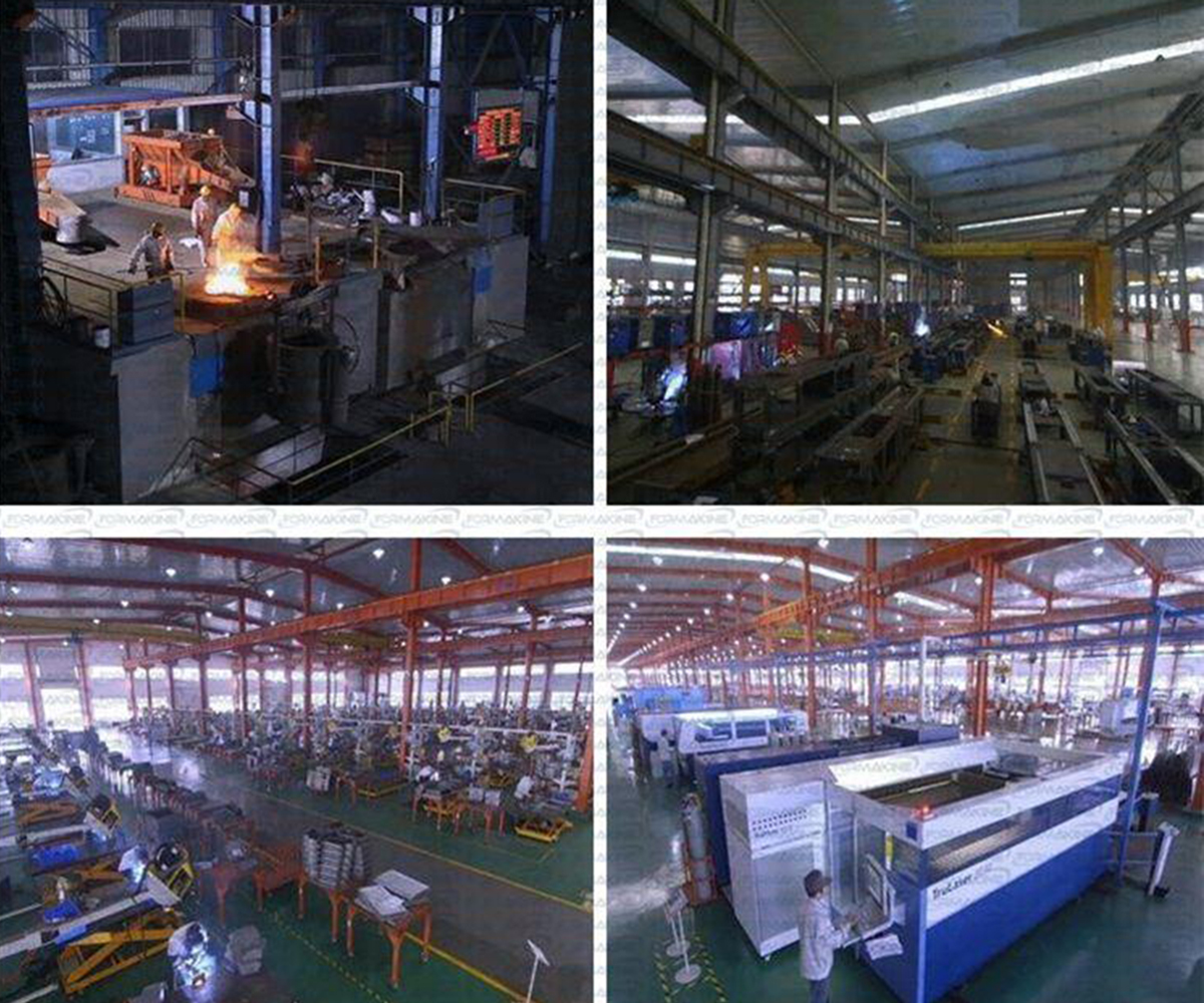
Our Factory
Packing & Shipping