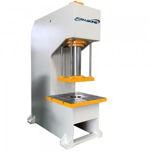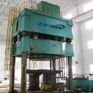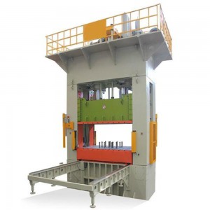
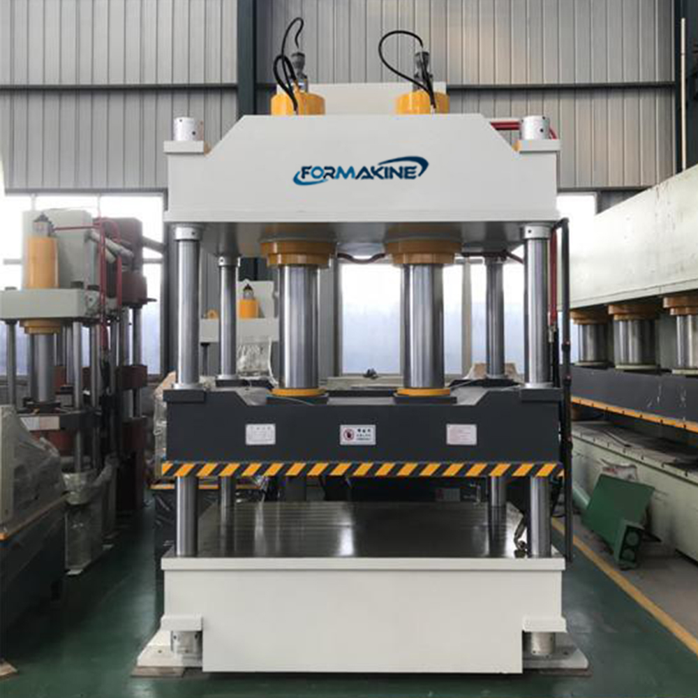
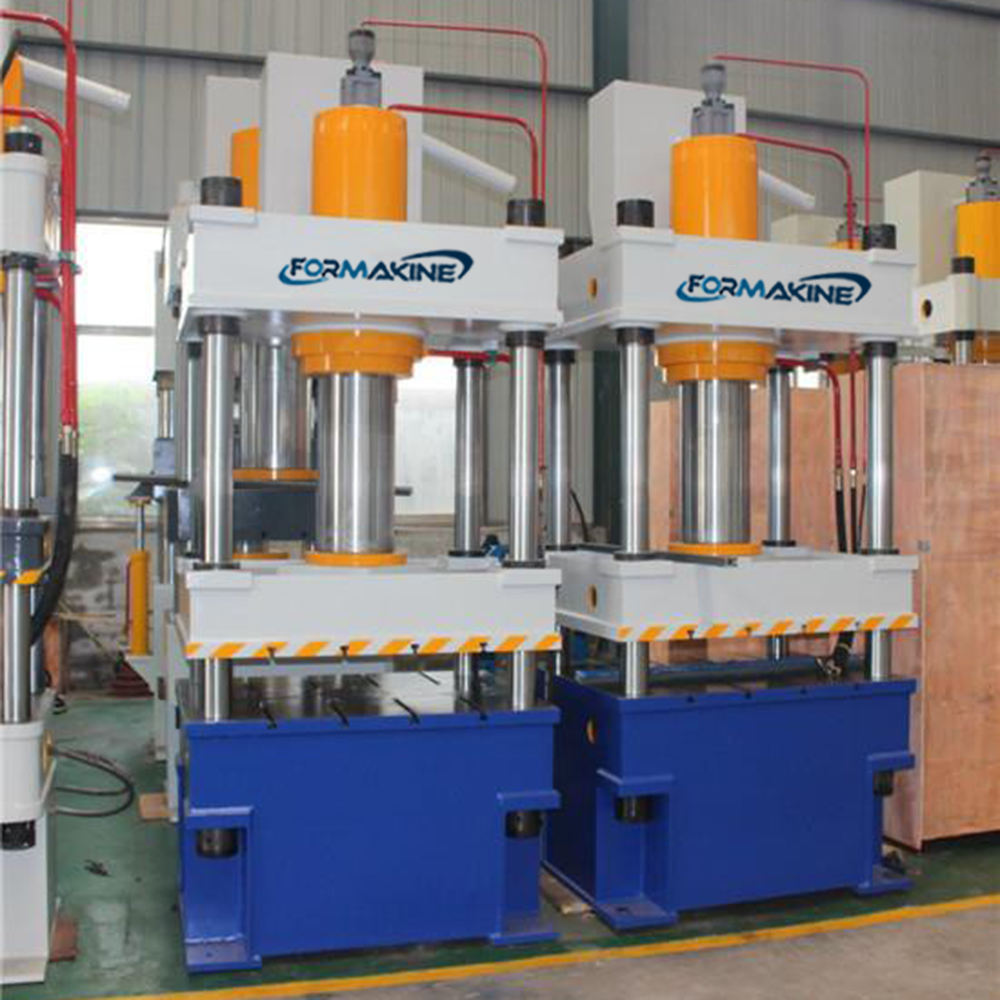
Four Column Hydraulic Stamping Press
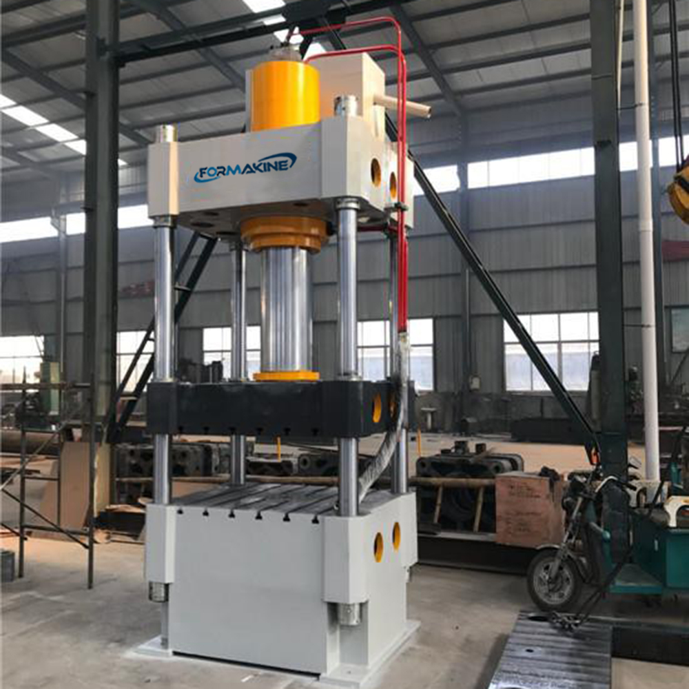
Product Features
Three-beam four-column structure, optimal design by computer, simple economical and applicable. The hydraulic control system uses cartridge valve integrated system, which has reliable action, long service life and small hydraulic impact and reduces linking pipeline and leaking points. The independent electrical control system is reliable in work, intuitive in action
and easy for maintenance. The button centralized control is used. Two operation modes of Adjusting (inching) and Single(semi-automatic)are set.Two molding technologies of constant stroke and constant pressure can be achieved, with performance of pressure maintaining and time delay, etc.The working pressure and stroke are adjustable in the specified range based on technological needs.
Applicable Fields
This series of hydraulic presses are widely used for drawing, bending flanging, cold extrusion, blanking, and other technologies of metal materials, as well as the compression molding of correction, press-fitting and powder products and abrasive products.
Optional Accessories
Blanking Buffer Device Movable Operating Platform Light Curtain
Safety Protection Device Oil Cooling Device Touch Industrial Display
Material Ramming Device Quick Fie Clamping Mechanism Imported PLC
Inhead Type Hydraulic System Slider Locking Mechanism
Floating Guide Rail and Roling Bracket for Die Replacement
Technical Specifications
| Item Type | Unit | Y32-40 | Y32-63 | Y32-100 | Y32-125 | Y32-200 | Y32-315 | Y32-400 | Y32-500 | Y32-630 | Y32-800 | Y32-1000 | Y32-1250 | |
| Nominal Pressure | KN | 400 | 630 | 1000 | 1250 | 2000 | 3150 | 4000 | 5000 | 6300 | 8000 | 10000 | 12500 | |
| Ejecting Force | KN | 100 | 160 | 630 | 630 | 800 | 800 | 800 | 1000 | 1000 | 1250 | 2000 | 2000 | |
| Knock-Out Force | KN | 150 | 125 | 160 | 180 | 360 | 450 | 345 | 570 | 850 | 720 | 1600 | 1200 | |
| The Max. Pressure Of Working Fluid | MPa | 25 | 25 | 25 | 25 | 25 | 25 | 25 | 25 | 25 | 25 | 25 | 25 | |
| The Max. Stroke Of Slider | Mm | 320 | 500 | 630 | 630 | 710 | 800 | 800 | 900 | 1000 | 1000 | 1000 | 1000 | |
| The Max. Stroke Of Ejector | Mm | 150 | 160 | 200 | 200 | 250 | 300 | 300 | 300 | 300 | 350 | 450 | 450 | |
| The Max. Opening Height | Mm | 520 | 800 | 900 | 900 | 1120 | 1250 | 1250 | 1500 | 1600 | 1600 | 1600 | 1800 | |
| Speed Of Slider | Descend | Mm/S | 55 | 115 | 250 | 220 | 160 | 120 | 180 | 150 | 120 | 150 | 150 | 250 |
| Working | Mm/S | 10-35 | 10-22 | 12-40 | 9-31 | 7-24 | 8-20 | 10-24 | 10-24 | 8-18 | 8-15 | 5-12 | 8-15 | |
| Return | Mm/S | 105 | 105 | 200 | 180 | 120 | 120 | 250 | 180 | 125 | 145 | 75 | 140 | |
| Speed Of Ejector | Ejecting | Mm/S | 170 | 90 | 120 | 60 | 60 | 75 | 120 | 65 | 65 | 50 | 60 | 45 |
| Return | Mm/S | 450 | 220 | 125 | 125 | 120 | 150 | 120 | 135 | 135 | 120 | 120 | 120 | |
| Active Area Of Working Table(E×D) | L-R | Mm | 450 | 570 | 710 | 710 | 930 | 1260 | 1300 | 1400 | 1880 | 1880 | 2000 | 2500 |
| F-B | Mm | 400 | 500 | 630 | 630 | 900 | 1200 | 1300 | 1400 | 1600 | 1600 | 1800 | 2000 | |
| Overall Dimension | F-B | Mm | 1230 | 1850 | 2100 | 2200 | 2350 | 2840 | 3600 | 3840 | 5230 | 5550 | 5946 | 8000 |
| The Height Between Working Table And Ground | L-R | Mm | 1234 | 1855 | 1880 | 1880 | 2000 | 2000 | 2600 | 2800 | 2800 | 2600 | 3135 | 3400 |
| F-B | Mm | 1115 | 2900 | 3260 | 3260 | 3520 | 4175 | 4800 | 4960 | 5257 | 5630 | 5614 | 7600 | |
| Height Above The
Ground
|
Mm | 870 | 800 | 860 | 860 | 550 | 650 | 710 | 500 | |||||